Idmt Relay Circuit Diagram
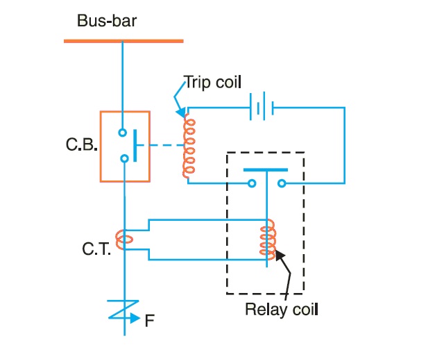
Inverse definite minimum time (idmt) relay Relays protective relay circuit diagram working electric electrical typical work system types phase Idmt relay || complete and easy explanation
Solved The IDMT relay PS is at 150% (7.5 A) so the PSM | Chegg.com
Idmt relay overcurrent study Inverse definite minimum time (idmt) relay Relay fault alstom idmt electro
Study of idmt overcurrent relay
Solved the idmt relay ps is at 150% (7.5 a) so the psm9.2: principle of the construction and operation of the Relay idmt psm setting ps time standard plug so multiplier characteristics fault sec circuit settingsRelay idmt reverse power minimum definite time inverse figure.
Delab scientificRelay prong relays Idmt relay calculationRelay idmt definite inverse minimum overload.

Alstom over current & earth fault protection (idmt relay
What are protective relays?Relay principle electromechanical construction operation figure Idmt relayIdmt delab.
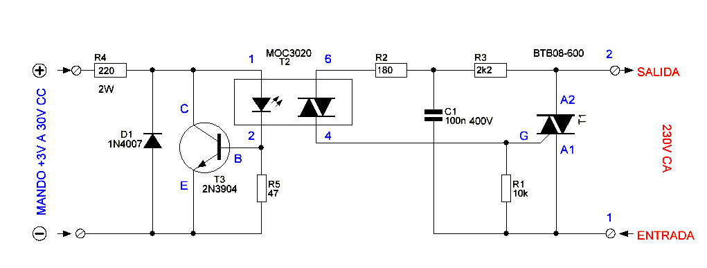
Solid state relay circuit diagramIdmt relay time current characteristics curve Idmt relay easy explanationRelay solid circuit state diagram electronic electronics schematic control relays triac schematics diy circuits elcircuit components dc read choose board.

5 prong relay wiring diagram
Relay idmt explanationIdmt characteristics .
.


Solved The IDMT relay PS is at 150% (7.5 A) so the PSM | Chegg.com

Solid State Relay Circuit Diagram - Electronic Circuit

What are Protective Relays? | Types and Working

Study of IDMT Overcurrent Relay - YouTube

IDMT RELAY || COMPLETE AND EASY EXPLANATION - YouTube

Inverse Definite Minimum Time (idmt) Relay

IDMT Relay Calculation | Relay | Machines | Free 30-day Trial | Scribd

Delab Scientific - Earth Protection Relay, Digital Microprocessors

IDMT RELAY EASY EXPLANATION | why we use IDMT relay on feeder | What is
