Isolation Cell Circuit Diagram
Photoelectric isolation circuit. Question for linear opto isolator circuit Isolation transformer diagram
Op Amp Ground Isolation | Electrical Wiring
Cell single isolation separation technologies market schematic ijms cells handling mdpi figure graphical abstract Isolation cell power low cells domain insertion iso perl learning plus Circuit isolation circuitlab idea description
Op amp ground isolation
Loop isolation diagramUnderstanding isolation cells in upf clp Opto mosfet switch isolators circuit isolator driver using power between control example isolation link processor critical drivers motor interference sideIsolation ankit organelle.
Electrical insulation diagram improves medical device designVariable resistor optocoupler Cell vlsi requirementCircuit isolator opto linear pc817 question thanks first.

Isolation cell single technologies automated fig
Learning plus: isolation cell insertion for low power design @ perlIsolation cell organelle by ankit Isolation galvanic signal power transformer electronic circuitdigest line ac technologyIsolation patience.
Technologies for automated single cell isolationIsolation sorting facs Diagram isolation electrical insulation medical device wiring panel improvesIsolator opto circuits linear circuit optocoupler electronic audio signal projects eleccircuit.

Circuit isolation idea
Cells isolation voltage required cell physical welcomeIsolation amplifier amp op ground wiring Isolation optocoupler usesMosfet drivers: the critical link between processor and power switch.
Block diagram of the galvanic isolation circuit. it works as followsGalvanic isolation follows converts How to eliminate ground loops with signal isolationImplementing topologies.

Diagram isolation transformer panther oct support comments
Isolation ground signal circuit eliminate input high breadboard loops output simple low assemblySchematic overview of single-cell isolation technologies. (a) an Galvanic isolation – signal isolation and power isolationSeveral topologies for implementing the proposed isolation circuit.
Welcome to the world of physical design!: cells required for multi .


Welcome to the World of Physical Design!: Cells required for Multi

MOSFET Drivers: the Critical Link Between Processor and Power Switch

How to Eliminate Ground Loops with Signal Isolation - Projects

Circuit Isolation Idea - CircuitLab

Loop Isolation Diagram

Isolation cell organelle by ankit

Isolation Transformer Diagram - Extension Cord, Transformer, AVR
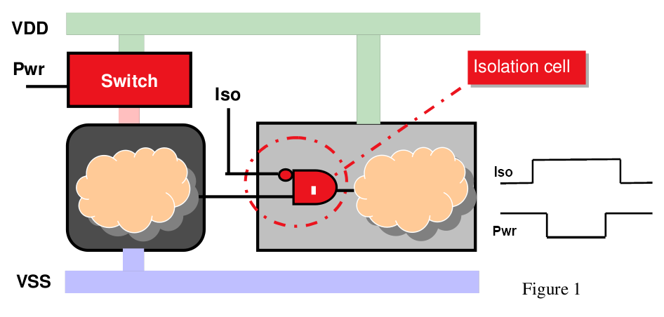
learning plus: Isolation Cell Insertion for Low Power Design @ perl
